Spring Fatigue Failure: Why Springs Break and How to Design for Long Fatigue Life
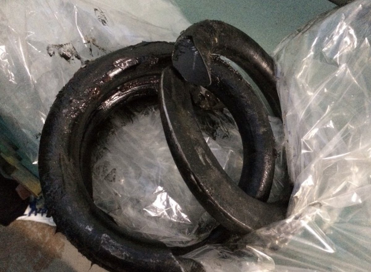
Every engineer who specs springs has seen it — or dreads seeing it: a spring that snapped in service, well before anyone expected. No overload event. No corrosion. Just… broke.
That's fatigue failure. And unlike a one-time overload, fatigue doesn't happen because someone made an obvious mistake. It happens because thousands of small decisions — material selection, coil geometry, surface finish, stress relief — added up the wrong way. The good news: it's almost entirely preventable if you understand the mechanism.
This article covers the science of spring fatigue, the six most common root causes, and seven proven strategies to make your springs last longer.
What Actually Happens When a Spring Fatigues
Fatigue failure follows a predictable — and surprisingly slow — three-stage sequence:
- Crack initiation: At a microscopic stress concentration — a surface scratch, an inclusion in the steel, a corrosion pit, or even a machining mark — the repeated tensile stress of each spring cycle begins to tear the metal's crystal lattice apart, atom by atom. This stage can last thousands or millions of cycles with no visible change to the spring.
- Crack propagation: Once a micro-crack reaches a critical size (typically 50–100 micrometers), each load cycle grows it a tiny bit further. The crack front advances perpendicular to the direction of principal tensile stress, creating the characteristic "beach marks" visible on fracture surfaces under a microscope.
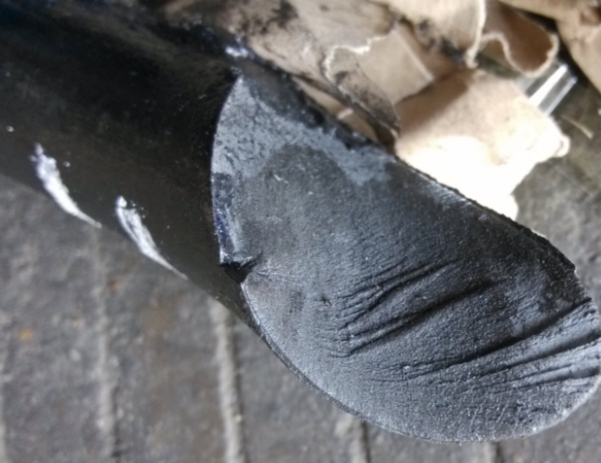
- Final fracture: When the remaining cross-section can no longer support the load, the spring snaps — suddenly and completely. The final fracture surface looks distinctly different from the fatigue zone: rough, granular, and often at a 45° angle to the wire axis.
The S-N Curve: A Spring Designer's Most Important Graph
Fatigue behavior is captured by the S-N curve (stress vs. number of cycles), also called the Wöhler curve after the German engineer who first mapped it in the 1860s. The concept is simple but the implications for spring design are profound:
- Higher stress = exponentially fewer cycles. A 15% reduction in stress can increase fatigue life by a factor of 10. The relationship is not linear — it's logarithmic.
- Some steels have a fatigue endurance limit. Below a certain stress threshold (typically 40–50% of ultimate tensile strength for music wire and chrome-silicon), the S-N curve flattens — the spring can theoretically endure infinite cycles. This is the holy grail of spring design.
- Stainless steels do NOT have a true endurance limit. Unlike high-carbon steels, 300-series stainless continues to fatigue slowly even at low stress levels. For stainless springs in dynamic applications, you must design to a specific life target — you cannot rely on an endurance limit.
6 Root Causes of Premature Spring Fatigue
When a spring fails early, the cause almost always falls into one of these categories:
⚠️ #1: Surface Imperfections
Fatigue cracks almost always start at the surface. A scratch, pit, tool mark, or even a rough mill finish can act as a stress raiser. This is the single most common cause of premature spring fatigue — and the reason shot peening (see below) is so effective at extending life.
#2: Material Inclusions & Defects
Non-metallic inclusions in the steel — sulfides, oxides, silicates — are stress concentrators embedded inside the wire. Premium spring-grade wire (ASTM A228 music wire, ASTM A401 chrome-silicon) is produced with much tighter inclusion controls than commercial-grade wire. The cost difference is real, but so is the fatigue-life difference: premium wire can deliver 3–5× the fatigue life of commercial-grade wire at the same stress level.
⚠️ #3: Inadequate Stress Relief
Cold coiling introduces residual tensile stresses in the spring, especially on the inside diameter of the coil. If these aren't relieved through proper heat treatment (typically 230–260°C / 450–500°F for 20–30 minutes for music wire), they add to the applied stress on every cycle, accelerating fatigue. Skipping stress relief on a dynamically-loaded spring is like driving with the parking brake on.
#4: Corrosion & Environmental Attack
Corrosion pits are ideal fatigue initiation sites. A spring that would last 10 million cycles in dry air might fail in 100,000 cycles in a humid or mildly corrosive environment. This is why passivation and, in severe cases, protective coatings are essential for stainless springs in challenging environments.
⚠️ #5: Coil Clash & Shock Loading
When a compression spring is compressed to solid height, the coils impact each other. At high cycling speeds, this impact creates a stress wave that can reach 2–3× the nominal stress. Over time, the contact points between adjacent coils develop flat wear spots and micro-cracks. The fix: design the spring so maximum working deflection stays below 80% of solid height, and use damper coils or progressive-rate designs when impact is unavoidable.
#6: Operating Too Close to the Tensile Limit
Sometimes the design simply asks too much. If the stress amplitude exceeds 40–50% of the wire's tensile strength, no amount of process optimization will guarantee long life. The fix is a design change: larger wire diameter, fewer active coils, different material, or a spring configuration that spreads the load (nested springs, variable pitch, etc.).
7 Strategies to Maximize Spring Fatigue Life
Ranked from highest impact to lowest, based on decades of fatigue testing data:
| # | Strategy | Typical Life Improvement | Cost Impact |
|---|---|---|---|
| 1 | Shot Peening — bombard the surface with microscopic steel or ceramic spheres, inducing compressive residual stresses that counteract tensile fatigue stress | 2–10× | Moderate |
| 2 | Reduce Stress Amplitude — larger wire, more coils, or lower working deflection to keep peak stress well below 40% UTS | 5–100× | Low–Moderate |
| 3 | Premium Wire Grade — specify ASTM A228 (music wire) or A401 (chrome-silicon) instead of commercial hard-drawn wire | 3–5× | Moderate |
| 4 | Proper Stress Relief — controlled oven tempering immediately after coiling; never skip for dynamic springs | 2–4× | Low |
| 5 | Surface Finish Improvement — electropolishing or fine grinding of critical surfaces to remove tool marks and scratches | 1.5–3× | Moderate–High |
| 6 | Corrosion Protection — passivation, electroplating, or epoxy coating depending on environment severity | 2–10× (in corrosive environments) | Low–Moderate |
| 7 | Presetting (Scragging) — compress the spring to solid height once during manufacturing to induce beneficial residual stresses | 1.2–1.5× | Very Low |
Deep Dive: Why Shot Peening Works
Shot peening deserves special attention because it's the single most effective fatigue-life improvement that doesn't require a design change. Here's the mechanism:
Fatigue cracks can only propagate under tensile stress. The spring surface — particularly the inside diameter of a compression spring coil — experiences peak tensile stress on every cycle. Shot peening bombards this surface with high-velocity spheres, plastically deforming a thin surface layer (typically 0.1–0.3 mm deep). When the spheres rebound, the underlying elastic material tries to return to its original shape, but the plastically-deformed surface layer resists — creating a residual compressive stress field.
When the spring is loaded in service, the applied tensile stress must first overcome this residual compressive stress before any net tensile stress reaches the surface. The result: the fatigue-sensitive surface layer "sees" a much lower stress range than the bulk material.
Key peening parameters that must be controlled:
- Shot size: Typically S70 to S230 (0.18–0.58 mm diameter) for spring wire from 1.0 to 10.0 mm
- Intensity: Measured by Almen strip arc height; typical range 0.2–0.6 mm A for springs
- Coverage: Must be ≥100% (every point on the surface hit at least once); 200% is common for critical applications
- Shot type: Cut wire shot (steel) for most applications; ceramic shot avoids iron contamination on stainless springs
Fatigue Testing: Verifying Life Predictions
Design calculations get you in the ballpark. Testing confirms you're actually in the stadium. The three standard methods:
- Constant-amplitude fatigue test: The spring is cycled between two fixed lengths (or loads) until failure or until a target cycle count is reached. This maps one point on the S-N curve and is the standard for production validation.
- Staircase method: Multiple springs are tested at incrementally decreasing stress levels to statistically determine the endurance limit. Requires 15–30 specimens but yields a statistically robust result.
- Block spectrum testing: The spring is subjected to a programmed sequence of varying loads that simulates real-world usage. Used when the application has a known duty cycle (e.g., an automotive valve spring that sees idle, cruise, and WOT conditions).
At AOFENG, our in-house fatigue testing machines handle springs from 1.0 mm to 12.0 mm wire diameter, at frequencies up to 30 Hz, with automated cycle counting and load monitoring. For every new dynamic-spring program, we recommend running a validation batch of 10–20 springs to confirm the design calculations before committing to full production.
When to Worry About Fatigue — and When Not To
Not every spring needs a full fatigue analysis. Here's a practical decision framework:
| Application Type | Cycles Expected | Fatigue Analysis? | Recommended Approach |
|---|---|---|---|
| Static spring (constant load) | <1,000 | No | Standard design to yield-strength safety factor |
| Low-cycle (e.g., latch spring) | 1,000–100,000 | Basic check | Keep stress below 50% UTS; standard stress relief |
| Moderate-cycle (e.g., suspension spring) | 100,000–1,000,000 | Yes | S-N curve analysis + shot peening recommended |
| High-cycle (e.g., valve spring, injector spring) | 1M–100M+ | Absolutely | Full fatigue design + premium wire + shot peening + validation testing |
| Safety-critical (e.g., brake, medical implant) | Any | Mandatory | Fatigue analysis + 100% validation + full lot traceability |
The Bottom Line
Spring fatigue is not random. It follows well-understood physical laws, and it leaves clear evidence on the fracture surface. If your springs are failing early, the root cause is almost certainly one of the six factors above — and the fix is almost certainly one of the seven strategies.
The most cost-effective moment to address fatigue is during the design phase. A $0.05 shot-peening operation on a $2.00 spring can save a $500,000 warranty claim. The math isn't complicated — but someone has to do it.
Need springs designed for long fatigue life?
Share your load, deflection, and cycle-life requirements with our engineering team. We'll help you get the design right before the first prototype is wound.
Talk to an Engineer