
Technical Guide
Valve spring set:
why seat pressure drops.
The spring that measured 280 N on the bench is not the spring the engine sees after a hundred thousand kilometres. Here is what changes the second number, how to measure it, and what to put on the drawing so it stops changing.
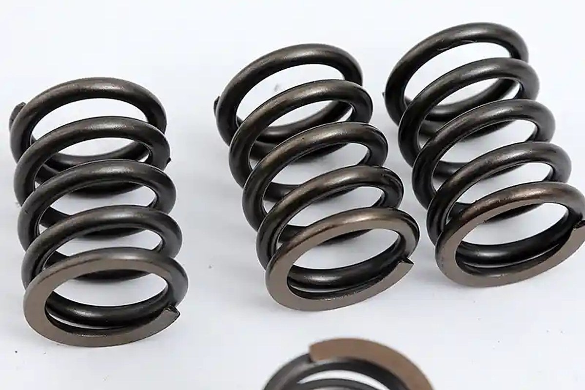
A valve spring has one number that matters more than any other: the load it holds with the valve closed. Seat load is what keeps the valve on its seat when the cam is not pushing it down. Everything else about the spring — free length, coil count, wire diameter, finish — exists to produce that number, and to keep producing it for the life of the engine.
Which is why the most common valve spring complaint is not breakage. It is that the spring measured correctly when it was made and measured low when it was pulled. Nobody changed the drawing. Nobody changed the wire. The spring simply lost load while it was bolted into a cylinder head, held at installed height, at engine temperature, for a few thousand hours.
That loss has a name, a mechanism and a set of design levers. This article covers all three — and ends with the list of values a valve spring drawing should carry if the supplier is to be held to the number the engine actually needs.
Two numbers, one spring
The first number is the load at installed height, measured on a spring tester at room temperature, before the spring has ever run. It is the number in the inspection report, and for most purchases it is the only number anyone checks.
The second number is the same load after the spring has spent time compressed in a hot cylinder head. It is lower. How much lower depends on the design, the material and the process — and on whether anyone asked for the second number at all.
A typical seat load tolerance on a production drawing is ±5%. A spring that loses 6% of its seat load in service is still perfectly within tolerance when it leaves the factory, and out of specification the moment the engine is hot. That gap is what this article is about.
Set, relaxation and sag are not the same thing
Three words get used interchangeably in valve train conversations. They describe three different behaviours, and they need three different countermeasures, so it is worth separating them.
| Term | What changes | When it appears | How it is measured |
|---|---|---|---|
| Set | Free length gets shorter; the spring does not return to its original height | First load cycles, and again on first exposure to heat | Free length and seat load before and after compressing to solid |
| Relaxation | Load drops while the spring stays at a fixed compressed length | Slowly, over hours and thousands of hours, faster when hot | Load at installed height before and after a defined time at temperature |
| Sag / creep | Continued slow length loss under sustained load | Late in life, usually after relaxation has already done its work | Free length at end of life, if the part is available |
In a valve spring all three are present at once, which is why a single “percent loss” figure without a test method is close to meaningless. A supplier reporting 2% loss may mean 2% after ten cycles at room temperature, or 2% after a hundred hours at 140 °C. Those are not the same claim.
Why a spring loses load at all
Spring steel is not perfectly elastic. When a coil is wound, the wire is bent past its yield point, and the material that comes off the coiler carries a residual stress pattern: tension on the inside of the coil, compression on the outside. Stress relief and tempering reduce that pattern, but they do not erase it, and the balance of what remains decides how the spring behaves under its first real load.
Three mechanisms act on that balance:
- Local yielding at solid height. At full lift, or during a preset operation, adjacent coils approach each other. Contact stresses at the coil faces are high and uneven, and the wire yields locally. When the load is released, those yielded regions do not spring back fully — the free length is now shorter, and every subsequent load at installed height is lower by the rate multiplied by that length change.
- Residual stress redistribution. The stress pattern left by coiling and heat treatment is not the pattern the spring will settle into under service load. The first cycles redistribute it, and the redistribution is permanent.
- Thermally assisted relaxation. At engine temperature, dislocations in the steel can move given enough time and enough stress. The spring creeps toward a slightly shorter free length. The rate rises steeply with temperature: a spring that is stable at 80 °C may lose meaningful load at 140 °C over the same interval.
None of these is a defect. They are properties of a loaded steel part at temperature. The design question is not whether they happen, but whether they happen before or after the customer’s acceptance test — and by how much.
The arithmetic of load loss
The link between a length change and a load change is the spring rate, and it is unforgiving. Take a valve spring with a 44 N/mm rate and a 280 N seat load at 38.0 mm installed height. If the spring sets by 0.4 mm — a change you cannot see with a rule — the seat load falls by 44 × 0.4 = 17.6 N, or 6.3%.
Scale that across rates and you can see why high-rate springs are more sensitive to set than low-rate ones:
| Spring rate | 0.2 mm set | 0.4 mm set | 0.8 mm set |
|---|---|---|---|
| 20 N/mm | 4 N | 8 N | 16 N |
| 44 N/mm | 8.8 N | 17.6 N | 35.2 N |
| 70 N/mm | 14 N | 28 N | 56 N |
| 110 N/mm | 22 N | 44 N | 88 N |
Against a 280 N seat load, 0.4 mm of set on a 70 N/mm spring is a 10% loss. That is the entire tolerance band and more, gone in a change of free length that no visual inspection would ever catch.
A note on free length tolerance
Free length is usually specified with a tolerance of a millimetre or so, because free length is a manufacturing outcome rather than a functional requirement. Seat load is the functional requirement, and it is measured at installed height. This is why a drawing that specifies free length tightly but seat load loosely has the emphasis backwards: the spring can sit inside the free length tolerance and still miss the seat load, or sit outside it and hit the seat load exactly.
What accelerates it
Loss is not a fixed property of a spring; it responds to six variables, and each one has a design or process lever attached to it.
| Factor | What it does | The lever |
|---|---|---|
| Stress at solid height | Higher contact stress yields more wire on each approach to solid | A lower rate for the same lift, or a thicker wire in a larger package |
| Operating temperature | Relaxation rate climbs steeply with temperature | Grade selection and, where the duty demands it, a heat-stable steel |
| Time under compression | Relaxation continues for as long as the load is held | Nothing in the spring — but the test should match the service interval |
| Wire grade | Silicon-bearing grades hold load better at temperature than plain carbon | 60Si2Mn where the valve train runs hot and stress is high |
| Residual stress after heat treatment | Incomplete stress relief leaves the spring closer to yielding | Stress relief and tempering controlled as a process step, not a formality |
| Finishing | Acid pickling and electroplating can introduce hydrogen; heat during coating can relax the spring further | Post-plate bake where the finish requires it; process order agreed with the supplier |
How to measure set and relaxation
The measurement is simple in principle and easy to get wrong in practice. The version that gives comparable results between suppliers looks like this:
- Measure free length (L0) and the load at installed height (F1).
- Compress the spring to solid height, hold for a defined period, and release.
- Re-measure free length (L1) and the load at installed height (F2).
- Report set as a percentage of free length: (L0 − L1) / L0, and load loss as (F1 − F2) / F1.
For relaxation, hold the spring at installed height at a specified temperature for a specified time, then measure the load at that height, still at temperature if the fixture allows it. Hot measurement matters: a spring measured after cooling can recover part of the apparent loss and flatter the result.
Two traps in comparing suppliers
The first is a different preset procedure. A supplier that compresses to solid and holds for ten seconds is testing something different from one that cycles to solid three times. The second is measurement temperature. Unless the hold temperature, hold time, number of cycles and measurement temperature are written into the specification, two suppliers can report honest numbers that cannot be compared.
At our plant, load at installed height and at full lift is checked on automatic spring testers, and fatigue testing is run to the load range and cycle count agreed at RFQ. Stress relief and tempering are controlled in-house. We state the test method alongside the number, because a load figure without a method is a claim rather than a measurement.
Six levers that reduce loss
Lower the stress at solid height
The single most effective change. Design the coil so there is still clearance at full lift and the stress when the coils do touch stays inside what the wire can carry — in practice a lower rate for the same lift, or a thicker wire in a larger package. The constraint is surge: a softer, longer spring has a lower natural frequency, so coil design is always a negotiation between load retention and dynamic behaviour. The valve spring application page works through that trade-off in detail.
Ask whether the spring is preset
Presetting — scragging — deliberately overloads the spring during manufacture so that the set happens in the factory rather than in the engine. It does not eliminate relaxation, but it removes the first, largest and least predictable part of the loss. If your supplier presets, ask at what stress and for how long; if they do not, ask why not.
Choose the grade for the temperature
65Mn, 72A and 82B are sound carbon spring steels for moderate duty. Where the valve guide area runs hot and stress is high, a silicon-bearing grade such as 60Si2Mn holds load better because its microstructure resists relaxation at temperature. Stainless grades solve a corrosion problem, not a heat problem, and have a lower modulus that changes the load-deflection relationship.
Protect the heat treatment
Stress relief that is incomplete, or a finishing step that adds heat after it, gives back part of what the heat treatment bought. The sequence matters as much as the temperature. Ask for the process route, not just the furnace setting.
Put a loss limit on the drawing
A requirement such as “seat load loss not to exceed X% after Y hours at Z °C” converts an engineering expectation into a testable acceptance criterion. Without it, the only number being verified is the one measured five minutes after coiling.
Verify with a test that matches service
A ten-second compression test tells you about first-cycle set. It tells you nothing about a spring that will sit compressed at 120 °C for the life of a truck engine. The test should reproduce the load, the temperature and the duration the part will actually see.
What the engine feels
Seat load is not an abstract quality number. It is the force that keeps the valve closed against the pressure in the port and returns the follower to the cam profile at the speed the engine is turning. When it falls:
- The valve starts to float at a lower engine speed, because the spring can no longer accelerate the valve train fast enough to follow the cam.
- Seat bounce increases, so the valve lands with a higher impact velocity and the seat and face wear faster.
- Valve train noise rises, and the knock is often the first symptom noticed.
- In the worst case the valve and piston lose their clearance at high speed.
This is why engine designers treat the seat load figure as a rev-limit number, and why a spring that is “within tolerance” but at the bottom of it can still be the wrong spring for a high-speed engine. The margin between the specified seat load and the load at which float begins is the design margin, and set consumes it silently.
What to put on the drawing
A valve spring drawing that will hold a supplier to the in-service number needs more than a diameter and a load. The list below is the one we work from at RFQ:
- Installed height and seat load, with tolerance on the load rather than the length.
- Open height and open load, or the rate, with the same tolerance discipline.
- Solid height, and the minimum clearance between coils at full lift.
- Free length, for reference.
- Preset requirement, if any, with the method.
- Set or relaxation limit after a defined time at a defined temperature.
- Operating temperature range in the valve guide area.
- Wire grade and wire tolerance — we work to JIS wire tolerances by grade.
- Finish, and any post-plate bake.
- Cycle-life target and annual volume, so the test plan can be sized to the programme.
With those values, the coil design, the material and the test plan can all be confirmed before a tool is set. Without them, the supplier is designing to an incomplete brief and the engine is the place where the gap gets discovered.
The bottom line
Valve spring set is not a manufacturing defect to be inspected out. It is a predictable response of loaded steel to stress and temperature, and it is governed by variables the drawing can control: solid-height stress, grade, heat treatment, preset and the acceptance test.
Specify the second number. A spring that holds 280 N on the bench and 262 N after a hundred hours at temperature is a different product from one that holds 278 N — and only one of them will still be in specification when the engine is hot.
If you are working through a valve spring design now, the valve spring application page covers the geometry side — seat load, open load, rate, surge and the materials we wind — while the fatigue guide covers what happens when the stress range, rather than the load level, is the limiting factor.
Need seat load to hold for the life of the engine?
Send the installed height, the seat and open loads, the operating temperature and the cycle target. We will confirm the coil design, the grade and the test plan before quoting.